Chapter 2: ASSEMBLY COMMANDS
2A: THE MAIN HARDWARE POINTERS
You may be quite familiar with the POKE command. For example POKE 53280,0:POKE 53281,2 gives out a border colour of black and a screen colour of RED. Well, this is triggered by the C64's hardware to change colours, etc. Assembly can do similar things. Depending on which hardware settings you wish to trigger in order to generate specific effects. Here is a table with a brief description of the hardware properties. These are HEX / POKE values which are using in following chapters and a brief description about these:
| HEX VALUE ($) | POKE VALUE | DESCRIPTION |
| $0314 to $0315 | 788 to 789 | Low and Hi byte IRQ interrupt vectors |
| $0400 to $07E8 | 1024 to 2023 | Screen RAM (Default inside screen BANK $03, BASIC, etc) |
| $07F8-$07FF | 2040 - 2047 | Sprite TYPE (Frame/animation) |
| $D000 to $D00F | 53248 to 53263 | Hardware sprite X/Y positions. Quick description: $D000 and $D001 - X/Y position for hardware sprite 0 $D002 and $D003 - X/Y position for hardware sprite 1 $D004 and $D005 - X/Y position for hardware sprite 2 $D006 and $D007 - X/Y position for hardware sprite 3 $D008 and $D009 - X/Y position for hardware sprite 4 $D00A and $D00B - X/Y position for hardware sprite 5 $D00C and $D00D - X/Y position for hardware sprite 6 $D00E and $D00F - X/Y position for hardware sprite 7 All sprite positions can move a max of 256 pixels. It is also possible to expand the X position using a sprite position expansion pointer inside rolled loops, etc. |
| $D010 | 53264 | Sprite X MSB position expansion. After a hardware sprite has reached position 256. An additional value can be triggered to $D010 in order to allow the sprite move out of the border area. |
| $D011 | 53265 | Vertical
screen position (VSP) or Screen / Bitmap mode / Screen hiding mode.
Sometimes disabling the screen can speed up routines. For example, if
you were a genius and wanted to create your own speed cruncher, you
chose to switch the screen off to speed up compression progress. Values
used vary: $00-$0F = Screen off $10-$1F = Standard charset mode with Screen on + Vertical screen position $30-$3F = Bitmap on + Vertical screen position $50-$5F = Extended Colour Background mode (ECM) - Uses only one character set, and uses additional colours inverted inside the character set. $70-$7F = Illegal opcodes for hiding screen visibility (Handy for soft scrolling techniques) |
| $D012 | 53266 | Raster position - Often used for generating screen splits. For example, displaying a logo at the top, and a standard charset at the bottom. The raster position can also be used for generating timing values should you not wish to use an IRQ Raster interrupt |
| $D013 |
53267 |
Used for lightpen or light gun. (I never used thi, and don't use it in this tutorial) |
| $D015 | 53269 | Enable/Disable sprites. Conditional 0's and 1's in binary can be used in an assembler to select which sprites should be enabled / disabled. |
| $D016 | 53270 | Horizontal screen position (Hires or Multicolor) $00-$0F = Hires screen position $10-$1F = Multicolour screen position |
| $D017 | 53271 | Sprite expansion Y. Conditional 0's and 1's in binary can be used in an assembler to select which sprites should be expanded vertically |
| $D018 | 53272 | Charset mode. Reads a charset from existing memory, and displays the new charset to the screen (Or bitmap) |
| $D019 | 53273 | IRQ Raster Interrupt vector 1 |
| $D01A | 53274 | IRQ Raster Interrupt vector 2 |
| $D01B | 53275 | Sprite / background priorities - Conditional 0's and 1's in binary can be used in an assembler to select which sprites should be in front / behind a character. Also note, if placing behind chars, sprites will only hide behind the character CHAR colour. |
| $D01C | 53276 | Sprite multicolour on/off - Conditional 0's and 1's in binary can be used in an assembler to select which of the sprite's multicolour should be enabled / disabled. |
| $D01D | 53277 | Sprite expansion X on/of - Conditional 0's and 1's in binary can be used in an assembler to select which sprites horizontal expansion should be enabled / disabled. |
| $D01E | 53278 | Sprite to Sprite collision - Conditional 0's and 1's in binary can be used in an assembler to select which sprites hits another sprite in range |
| $D01F | 53279 | Sprite to Character collision - Conditional 0's and 1's in binary can be used in an assembler to select which sprites hit a visible character in range. NOTE: For hardware a character, which uses a changeable character colour set up will enable collision. |
| $D020 | 53280 | Border colour - There are 15 different colours to set the border. Colours are in the following order: $00 = Black, $01 = White $02 = Red, $03 = Cyan, $04 = Magenta/Purple, $05 = Dark Green, $06 = Dark Blue, $07 = Yellow, $08 = Orange, $09 = Brown, $0A = Pink, $0B = Dark Grey, $0C = Medium Grey, $0D = Light Green, $0E = Light Blue, $0F = Light Grey |
| $D021 | 53281 | Background colour - There are 15 different colours to set the background colour. Colours are listed in the above table (See Border Colour - $D020) |
| $D022 | 53282 | Charset Multicolour 1 (Can also be Extended Background Colour 1) - 15 colours |
| $D023 | 53283 | Charset Multicolour 2 (Can also be Extended Background Colour 2) - 15 colours |
| $D024 | 54284 | Extended Background Colour 3 (If using EBC mode) |
| $D025 | 54285 | Sprite multicolour 1 (If sprite multicolour ($D01C) is enabled). This is also a permanent colour chosen for each multicoloured sprite. |
| $D026 | 54286 | Sprite multicolour 2 (If sprite multicolour ($D01C) is enabled. This is also a permanent colour chosen for each multicoloured sprite. |
| $D027-$D02E | 54287- 53294 | Sprite colour - Sets the actual colour of a sprite hires/multicolour. - 15 colours (See $D020 for list of colours to choose from) |
| $D030 | 53295 | 2Mhz Mode for C128 |
| $D400 | 54272 | SID - Frequency Low (Channel 1) (Min #$00, Max #$FF) |
| $D401 | 54273 | SID - Frequencey High (Channel 1) (Min #$00, Max #$FF) |
| $D402 | 54274 | SID - Pulse / Low (Channel 1) (Min #$00, Max #$FF) |
| $D403 | 54275 | SID - Pulse / High (Channel 1) (Min #$00, Max #$FF) |
| $D405 | 54276 | SID - Wavefore (Channel 1) Values: #$00 - No wave #$11 - Triangle #$21 - Sawtooth #$31 - Trombone #$41 - Pulse wave V1 #$51 - Pulse wave V2 #$61 - Pulse wave V3 #$81 - White Noise Different combinations of wave form can be used to make ring sync voice effects. |
| $D406 | 54277 | SID- Attack/Decay (Min #$00, Max #$FF) |
| $D407 | 54278 | SID - Sustain/Release (Min #$00, Max #$FF) |
| $D409 - $D414 | 54279 - 54292 | SID - See all tables $D400-$D407 to find out more |
| $D415 | 54293 | SID - Filter Low byte |
| $D416 | 54294 | SID - Filter High byte |
| $D417 | 54295 | SID - Filter pass band |
| $D418 | 54296 | SID - Volume |
| $D800 - $DBE7 | 55296 - 55527 | Screen Colour RAM (Hardware colour positions for placing colours of your character sets on to the screen) |
| $DC00 | 56320 | Joystick Port 2 / Key map X |
| $DC01 | 56321 | Joystick Port 1 / Key map Y |
| $DD00 | 56576 | Screen BANK area Default (When booting up your C64 is BANK #3) ... Some tips: If unchanged character mode (Default = #$14): BANK #$03 uses $0400-$07e8 for screen RAM, $07F8-$07FF for HW sprite frames BANK #$02 uses $4400-$47E8 for screen RAM, $47F8-$47FF for HW sprite frames BANK #$01 uses $8400-$87E8 for screen RAM, $87F8-$87FF for HW sprite frames BANK #$00 uses $C400-$C7E8 for screen RAM,. $C7F8-$C7FF for HW sprite frames |
BACK TO TOP
You will notice other hardware pointers which are not featured in the table. These are basically things I can sort of remember in my head.
2B. SOME BASIC ASSEMBLY COMMANDS
When you are writing your own programs, it would usually be the best thing to take a look at various resources, so that you can understand all these following: commands. I can explain a few of these, but not all of them.
LOAD ACCUMULATOR FUNCTIONS (LDA, LDX, LDY)
LDX = LOAD VALUE TO ACCUMULATOR AS X
LDY = LOAD VALUE TO ACCUMULATOR AS Y
STORE ACCUMULATOR FUNCTIONS (LDA, LDX, LDY)
STA = STORE LOADED VALUE FROM ACCUMULATOR
STX = STORE LOADED VALUE FROM ACCUMULATOR TO X
STY = STORE LOADED VALUE FROM ACCUMULATOR TO Y
RTS = Return To Subroutine
Exits a current subroutine, and continues any other existing subroutines.
Whenever you want to POKE a command. In assembly, you would need to LDA a value the STA it to either a hardware pointer, self-mod position or a zero page. A small example shows you different ways you could learn this technique.
LOAD IN YOUR CROSS ASSEMBLER AND TRY THESE EXPERIMENTS:
EXAMPLE 1: Making a black border and background on your C64's screen using LDA only
!TO "BLACKBORDER1.PRG",CBM
*=$0810 ;SYS2064 to start
LDA
#$00
;Load the value colour BLACK to accumulator
STA
$D020 ;Store to BORDER COLOUR
STA
$D021 ;Store to BACKGROUND COLOUR
RTS ;Return to subroutine (Or end)
Quite simple eh? I'm sure it is. You cannot just LDA and STA, you can also use LDX and LDY and instead of use STA, you can use STX or STY, for example:
EXAMPLE 2: Making a black border and background on your C64's screen using LDX!TO "BLACKBORDER2.PRG",CBM
*=$0810 ;SYS2064 to start
LDX
#$00
;Load the value colour BLACK to accumulator X
STX
$D020 ;store the loaded accumulator X to H/W BORDER COLOUR
STX
$D021 ;store the loaded accumulator Y to H/W BACKGROUND COLOUR
RTS ;Return to subroutine
Assemble, and the SYS2064 again. Yet again, the same effect. A black border and black screen.
EXAMPLE 3: Making a black border and background on your C64's screen using LDY!TO "BLACKBORDER3.PRG",CBM
*=$0810 ;SYS2064 to start
LDY
#$00 ;Load the value colour BLACK to accumulator Y
STY
$D020 ;store the loaded accumulator X to H/W BORDER COLOUR
STY
$D021 ;store the loaded accumulator Y to H/W BACKGROUND COLOUR
RTS ;Return to subroutine
EXAMPLE 4: Using 2 combinations to display the border and background
Let
us say for example
you wanted to draw a black screen, but you want a red frame. You could
use LDA and STA like as the example below:
!TO "REDNBLACK.PRG",CBM
*=$0810 ;SYS2064 to start
LDA
#$02
;Load Colour value Red to accumulator A
STA
$D020 ;Store to BORDER COLOUR
LDA
#$00 ;Load Colour value Black to accumulator A
STA
$D021 ;Store to BACKGROUND COLOUR
RTS ;Return to subroutine
EXAMPLE 5: Displaying the border/background using X,Y combinations.
Although some programmers tend to get used to the old LDA, STA modules. Sometimes code can look slightly more tidy and possibly save cycles by using a combination of loading and storing accumulators A,X,Y. The example below shows a much tidier method to display a red border and black background through an assembler.
!TO "REDNBLACK2.PRG",CBM
*=$0810 ;SYS2064 to start
LDX
#$02
;Load value colour RED into accumulator X
LDY
#$00 ;Load value colour BLACK into accumulator Y
STX
$D020 ;Store loaded accumulator into border colour X
STY
$D021 ;Store loaded accumulator into background colour Y
RTS
There, that is
MORE tidy, but when you use this method. Please remember to be very
careful with it, otherwise you could end up writing a typo error, which
might look something like this. This will confuse the program running,
and give you some weird results. There is a theory that the LDX + LDY
before STX and STY could save cycles processed by the C64's hardware.
LDX
#$02
LDX #$02
LDX
#$00
or LDX #$00
STX
$D020
STX $D020
STY $D021
STX $D021
INCREMENT ACCUMULATOR X (INX), INCREMENT ACCUMULATOR Y (INY)
These
are two command
that are use to increment a value which can be inside a timed loop.
These
can
also be used for continuous moving of objects, flashing, rasters,
unrolled loops etc. Basically a loaded accumulator in either X or Y can
be incremented upwards. For example:
EXAMPLE 6: Using INX to increment values of a current value inside an accumulator
!TO "CHANGEBORDER.PRG",CBM
*=$0810 ;SYS2064
LDX #$00 ;Load accumulator X as Black
INX ;Increment one byte in the accumulator
STX $D020 ;Store new accumulator value to border colour
RTS ;Return to subroutine
The
example above shows that the border colour was originally to be
coloured black, however it increments the Loaded X accumulator by one
byte, making X as #$01. Therefore making the border colour white.
Try and replace LDX, INX and STX with LDY, INY, and STY to see what happens? Not much of a difference. That is because also values of Y are used. Now if you mix X and Y like this example below. You won't get very far:
EXAMPLE 7: Using LDY, INX, STY incorrectly to Example 6!TO "CHANGEBORDER2.PRG",CBM
*=$0810 ;SYS 2064
LDY #$00 ;Load accumulator Y as black
INX ;Increment one byte in the accumulator
STY $D020 ;Store new accumulator value to border colour
RTS ;Return to subroutine
COMPARE VALUE TO (CMP) (CPX)(CPY)
CMP compares a value of a certain amount. Detecting whether or not a loaded value in either an accumulator A, X, Y (Depending how you wish to use these) is used.
CPX compares a value of the loaded accumulator X
CPY compares a value of the loaded accumulator Y
BRANCH NOT EQUAL TO (BNE)
When
using CMP, you can also check that a branch doesn't equal a certain
value. For example. Comparing a value of a pointer with another. If no
match, then BNE is called to move on to one subroutine, otherwise
continue with another. This example shows me storing a pointer of a
value. If the value does NOT equal the selected colour. Do not change
the colour of the border. Otherwise the code will change the colour of
the border.
!TO "BORDERCHECK.PRG",CBM
*=$0810 ;SYS 2064
LDA #$02 ;Enter colour value RED into the accumulator
STA MYCOLOUR ;Store it to pointer MYCOLOUR
LDA MYCOLOUR ;Load pointer MYCOLOUR into the accumulator
CMP #$03 ;Compare the value of MYCOLOUR
BNE NOCHANGE ;Branch Not Equal to #$03 (Cyan) Go to label NOCHANGE
STA $D020 ;Else store current value to the border colour
NOCHANGE
RTS
MYCOLOUR !BYTE $00 ;Pointer for storing my colour
So then, what happened? Well, the colour RED was stored into pointer MYCOLOUR, and the program checks to see whether or not the colour matched CYAN. Because it didn't match CYAN, no change to the border colour was made. Now try and change the value of the LDA accumulator before storing it into MYCOLOUR. Replace it with the number #3. What happens? A cyan border will be displayed. Now have a little play around with the source and see what else happens.
BRANCH IS EQUAL TO (BEQ)
The command BEQ means branch is equal to. Say for example looking at the routine above, you wanted to change the code to check that the accumulator is EQUAL to a value. It would look something like this:
EXAMPLE 8: USING A POINTER, AND CMP, BEQ COMMAND
!TO "BORDERCHECK2.PRG",CBM
*=$0810 ;SYS 2064
LDA #$02 ;Enter colour value RED into the accumulator
STA MYCOLOUR ;Store it to pointer MYCOLOUR
LDA MYCOLOUR ;Load pointer MYCOLOUR into the accumulator
CMP #$03 ;Compare the value of MYCOLOUR
BEQ CHANGE ;Branch equals to colour
RTS ;Else return from subroutine
CHANGE
STA $D020 ;Store current value to the border colour
RTS
BPL, BCC & BCS (Higher / Lower than)
If you are familiar with BOOLEAN operators, then it is possible to compare a value is greater or lower than another value. For example in BASIC A number too high = red border, else green border you could say:10 N=4
20 IF N>7 THEN POKE 53280,2:END
30 POKE 53280,5:END
What if we wanted to do it in assembly form? Well, we type it like this:
EXAMPLE 9: USING BPL TO CHECK FOR LOWER POSITION
!TO "BORDERCHECK3.PRG",CBM
* =$0810 ;SYS2064
LDA #$02 ;Enter colour value RED into the accumulator
STA MYCOLOUR ;Store it to pointer MYCOLOUR
LDA MYCOLOUR ;Load pointer MYCOLOUR into the accumulator
CMP #$07 ;Compare the value of MYCOLOUR
BPL LOWER ;Branch is lower
LDA #$02 ;Load colour RED to accumulator
STA $D020 ;Store current value to the border colour
RTS ;Else return from subroutine
LOWER
LDA #$05 ;Load colour Green to Accumulator
STA $D020 ;Store current value to the border colour
RTS
MYCOLOUR !BYTE $00
Now that was easy, but what if you wanted to check whether or not a value was lower or higher than a set amount. We can use BCC and BCS to select a range of a lowest point, and highest point of a value. For example a small snippet below from one of the later chapters indicates the end position of an enemy sprite X position and enemy sprite Y position, representing a BOXED collision range.
No need to copy this subroutine - it is just a little example:
LDX #$00
LOOP
LDA ENEMYPOS+$00,x
CMP COLLISION
BCC NO_COLLISION
CMP COLLISION+$02
BCS NO_COLLISION
LDA ENEMYPOS+$01,x
CMP COLLISION+$03
BCC NO_COLLISION
CMP COLLISION+$04
BCS NO_COLLISION
INC $D020
RTS
NO_COLLISION
INX
INX
CPX #$10
BNE LOOP
But what has this got to do with an example subroutine I did with the border and background trickery? Well, a sort of similar case. If a value is higher than 7 or 8 set border colour to red, else if lower, set it to green:
EXAMPLE 11: USING CMP, BCC, BCS, BEQ!TO "MULTIPLECHECK.PRG",CBM
* =$0810 ;SYS2064
LDA #$02 ;Enter colour value RED into the accumulator
STA MYCOLOUR ;Store it to pointer MYCOLOUR
LDA MYCOLOUR ;Load pointer MYCOLOUR into the accumulator
CMP #$07 ;Compare the value equal to 7
BEQ OKAY ;Branch equals 7 - go to OKAY
CMP #$07 ;Compare the value of MYCOLOUR
BCC DORED ;Branch is lower
CMP #$07 ;Compare the value again
BCS DORED ;Branch is higher
RTS
OKAY
LDA #$05 ;Load colour GREEN to accumulator
STA $D020 ;Store current value to the border colour
RTS ;Else return from subroutine
DORED
LDA #$02 ;Load colour RED to Accumulator
STA $D020 ;Store current value to the border colour
RTS
MYCOLOUR !BYTE $00
JUMP SUBROUTINE (JSR)
The
JSR routine stands for JUMP SUBROUTINE. In BASIC terms we call it a
GOSUB. In assembly, we use the JSR function along with RTS (Return from
Subroutine). Here is a simple example, calling a subroutine to set a
border colour and background another colour. Say Dark Blue, and Purple
for example
EXAMPLE 12: USING JSR and RTS
!TO "JUMPSUBR.PRG",CBM
*=$0810 ;SYS2064
JSR BLUEBOR ;Jump subroutine for blue border
JSR PURBGD ;Jump subroutine for purple background
RTS ;Return to subroutine/exit
BLUEBOR
LDA #$06 ;Load accumulator A to #$06 (Dark blue)
STA $D020 ;Store accumulator A to BORDER COLOUR
RTS ;Return to subroutine/exit current routine
PURBGD
LDA #$04 ;Load accumulator A to #$04 (Purple/Magenta)
STA $D020 ;Store accumulator A to BACKGROUND COLOUR
RTS ;Return to subroutine
In BASIC we say GOTO line no XX. In assembly the command JMP acts the same way. It is used to jump to another subroutine, but it cannot call other subroutines inside a same subroutine, unlike JSR. Instead JMP
EXAMPLE 13: USING JMP WITH SIMILAR ROUTINE
!TO "JUMPSUB2.PRG",CBM
* = $0810 ;SYS2064
JMP BLUEBOR
PURBGD
LDA #$04 ;Load accumulator A to #$04 (Purple/Magenta)
STA $D020 ;Store accumulator A to BACKGROUND COLOUR
RTS
BLUEBOR
LDA #$06 ;Load accumulator A to #$06 (Dark blue)
STA $D020 ;Store accumulator A to BORDER COLOUR
JMP PURBGD
CALCULATING AND ADDING VALUES (CLC, ADC)
When
writing programs you might want to add a certain value of a
pointer/zeropage and store a new value to exactly the same pointer or
different pointer/zeropage. Adding results to:
LDA MYVALUE
CLC
ADC #1 ;Add amount by quantity
STA MYVALUE
MYVALUE !BYTE 0
REVERSE CALCULATING AND SUBTRACTING VALUES (SEC, SBC)
Also
when writing programs, you might also want to subtract to a certain
value of a pointer/zeropage and store a new value to exactly the same
pointer/zeropage or a differed pointer/zeropage. A basic subtraction of
a value is basically the same example above:
LDA MYVALUE
SEC
SBC #1 ;Subtract amount by quantity
STA MYVALUE
MYVALUE !BYTE 0
SET IRQ INTERRUPT (SEI )
turns
off an IRQ
interrupt flag, when a loop is inside the program. The best way to kill
of a complete kernal interrupt (If using $0314/$0315) would be to do as
follows:
REMEMBER THIS ANY TIME YOU NEED TO SWITCH OFF A KERNAL INTERRUPT OR EXISTING SOUNDS!!!
SEI
LDA #<$EA31 ;Set low +
LDX #>$EA31 ;hi bytes of $EA31 interrupts
STA $0314 ;Store IRQ Vector Low
STX $0315 ;Store IRQ Vector Hi
LDA #$81 ;Clear CIA chip
STA $DC0D
STA $DD0D
LDA #$00 ;ACK Raster interrupt to switch
STA $D01A ;off.
STA $D019
LDX #$00 ;Loop to silence the SID chip
SILENCE
LDA #$00
STA $D400,X
INX
CPX #$18
BNE SILENCE
CLI ;Clear IRQ flag
JSR $FF81 ;Soft reset screen (Default blue border/background)
RTS
CLEAR IRQ FLAG (CLI
)
Clears
registers and
allows the programmer to insert additional commands, which they cannot
use inside an IRQ loop! (See above example)
PHA, PLA
These
are special copy and paste commands. It basically copies a single value/byte and then pastes the value to somewhere. A little example:
!TO "PHAPLA.PRG",CBM
*=$0810
LDA #$02 ;Load colour red
PHA ;place into c64's memory
LDA #4 ;Load colour purple
STA $D020 ;Store colour purple to BORDER COLOUR
PLA ;Get first colour from memory
STA $D021 ;Store colour red to BACKGROUND COLOUR
RTS
PLA should always be repeated after PHA otherwise your program may crash. PHA+PLA can also be used inside interrupts as well.
It is time to writing your first program:
We are going to write our first program, which is just something small and simple. This program shows you how to create your own flashing border, while asking for the user to press the space bar. After the space bar is pressed the program will exit. So load up your assembler and type in the following listing, then assemble and run.
EXAMPLE: HELLO WORLD (Oh no! - Not again!!!)
Picking an assembler of your own choice, we are going to do a simple little program, which will clear the screen (SOFT SCREEN CLEAR) and then display a HELLO WORLD message on the screen. In order to display the message on to the screen. We shall use the screen RAM.
EXAMPLE: HELLO WORLD
;Not another
;Hello world by Richard/TND
!to "hello.prg",cbm
*=$0810 ;SYS2064
SEI
LDA #$37 ;Kernal mode ON
STA $01
LDA #$00 ;Black into accumulator
STA $D020 ;Store to border colour
STA $D021 ;Store to background colour
JSR $E544 ;Clear screen H/W kernal
LDA #$16 ;Flip case to charset
STA $D018
;Setup the text to display to screen
LDX #$00 ;Load accumulator X as value of 0
DISPTEXT
LDA HTXT,X ;Read text data
STA $0400,X 'Place to screen RAM area
INX ;Increment X
CPX #HTXTEND-HTXT ;Size of text before end placed
BNE DISPTEXT
RTS
!CT SCR ;Convert PETSCII/ASCII to CBM Screen characters.
HTXT !TEXT "hello world ... richard was here!"
HTXTEND
That was a typical HELLO WORLD text. This was just a basic screen print test. Try changing the text (keeping the HTXTEND underneath) and see what happens. Also try and play with the screen values $0400 - $07e8 and see what you can get.
BACK TO TOP
BORDER FLASHING
You remember the border colours examples from above. We are going to do something more interesting and basically very simple. The next program below is going to show you how to FLASH the entire border with a series of colours. All 16 of them in fact. Remember some of the tape loader errors, like Wild save, where the screen flickered multi colours. Well, we are going to do this with rainbow colours. The program will start with SYS2304 ($0900) and then start flashing the screen. Pressing the space bar should stop it from flashing and exit the program. Why not give this code a try :)
;===================
;RAINBOW
COLOURS
;===================
!to "ranbowcolours.prg",cbm
* = $0900 ;SYS2304
SEI ;CLEAR IRQ
LOOP
INC $D020; INCREMENT BORDER
LDA $DC01; CHECK BUFFER
CMP #$EF ; IS SPACE PRESSED ($DC01 = #$EF)?
BNE LOOP ; IF NOT THEN JUMP TO LOOP AND FLASH AGAIN
RTS ; IF SPACE IS PRESSED THEN END
RESULT:
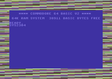
Can you see how easy it is to create your own short program? Now all you need to do is assemble the program and run it. Guess what? You'll see a flashing border. The border will continue to flash until you press space. Then the program will finish. Well why does the program continue flashing, before SPACEBAR is pressed? Well, that's easy, because the program is inside a control loop, which continues to loop until the value #$EF is found, and then the C64 stops running the program, as the program tells it to do so. Now why not try deleting LDA $DC01, CMP #$EF and BNE LOOP into:
METHOD 2:
;===================
;RAINBOW
COLOURS
;===================
!TO "RAINBOWCOLOURSV2.PRG",CBM
* = $0900 ;SYS2304
SEI
;CLEAR IRQ
LOOP
INC $D020 ; INCREMENT BORDER
LDA $DC01 ; CHECK SPACEBAR
LSR
; If SPACEBAR IS NOT
LSR
; PRESSED THEN JUMP
LSR
; TO THE LOOP!
LSR
LSR
BCS LOOP
RTS
Not much of a difference there, but this is also checking for a button on joystick port 1. Yes, that's right FIRE BUTTON. The spacebar will still work.
I would prefer to use method 1, in order of processing the code. This is because it is shorter compared to method 2. Shorter routines can compress the program, which you write. It also saves the amount of memory that has been used in an assembler.
Flashing Borders Using X+Y loops
As you noticed just a while ago. I gave
you an example program that allows you to flash the colour borders,
but now, I'm going to show you how you can EXPAND colour sizes. Here is
what we'll do. We shall use an LDX prompt and also an LDY prompt (for X
and Y loops). We shall still use INC $D020 and INC $D021 and the
pressing
spacebar method, but this is just a little taster of what we have in
store
for this section :o)
;==================
;FLASHING
BORDERS
;USING
X & Y LOOPS
;==================
!TO "COLOURTABLE.PRG",CBM
*=$0900 ;SYS2304
SEI
MAINLOOP
LDX
#$00
;Set 'X' as 0
LOOPX
LDY
#$00
;Set 'Y' as 0
LOOPY
INC
$D020
;Flashy border
INY
;Increment Y
CPY
#$77
; Is 'Y' equal to #$77
BNE LOOPY ; If not then
Y=Y+1, goto LOOPY
INX
; Increment X
CPX
#$77
; Is 'X' equal to #$77
BNE LOOPX ;If not then
X=X+1, goto LOOPX
LDA $DC01
;Load
Spacebar command
CMP
#$EF
;Is spacebar pressed
BNE MAINLOOP ; If not then jump to the MAINLOOP prompt
RTS
; else END program operation
You will notice that there wont be much of a difference in the flashing borders. However, we could try something different. Here is what to do.
Underneath RTS, build your own colour table. Include the label COLOURS. You could try the following:
COLOURS
!BYTE $00,$06,$0E,$03
!BYTE $03,$0E,$06,$00
Now let's try a little experiment shall we?
Where we have
INC
$D020,
replace this with LDA COLOURS,X and then add STA $D020. We're not
finished
there yet. In order to read the amount of colours that are in the
colour
table, the next thing for you to do is change CPY #$77 to CPY #$27 and
then change CPX #$77 into CPX #$08.
Now
let's test it ;o)
RESULT:
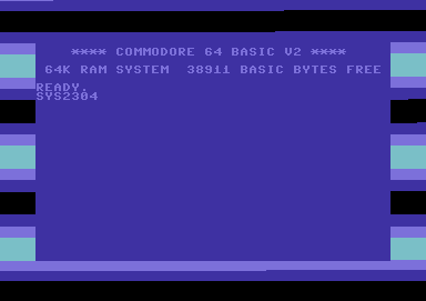
Now, why not try and change CPY #$08 and see what happens next ;o) Notice any differences? The border thins down and it scrolls something like those colour bars, which have been used on SEUCK games apart from SEUCK bars go upwards instead of downwards.
Thinning colour bars, etc is plain easy to handle, but when $D012 is involved, things change.
The borders look a mess, as they are flickering so what should be done now is some minor adjustment to the flickers. All we do is add NOP, a few times, until the borders are nice and straight. Let's try it. Erm, no, as not much effort would be put into it. Maybe using $D012 would help. We'll look at this later on when it comes to raster splits.
More tutorials and code on the next page. - Which is even more fun. It is all about drawing on the screen, and using rasters.
Next Page / Previous Page / Back to page of contents