
CHAPTER 4
Raster Splits, Colour Bars and coding your own simple Demos and Intros
A raster split is a hardware command that can create amazing things. For example a C64 demo uses raster splits and interrupts. A raster split is triggered by using the $D012. If you ever bought or seen a C64 game in the 1980's and 1990's, you will have noticed that some front ends, or most use rasters to cut the screen. $D012 is known for it's clever features, such as screen cuts, raster bars, control inside an interrupt etc.
An example:
This is the fun bit. $D012 is used to create some raster splits. For example, if you wanted to make your own title screen for a C64 game, you would need to code in the raster splits. Let us say for example, you paint a logo using drawing programs, save them as a VIDCOM format and you want to display the normal font you created which is located at $2000. A raster split would need to be used, therefore you would need to split everything up. For example, a way a screen would be presented.:
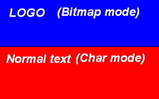
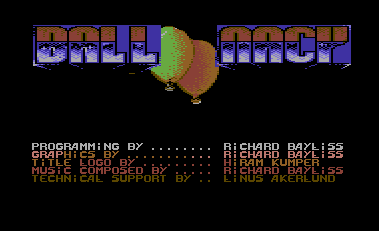
If you look at the black line, you can see that this design represents the co-ordinates of the raster split. A prime example for something like this is a title logo, which was done for the game Balloonacy. Look below and you'll see what I mean by a raster split :o)
Now we are going to try something similar, but more simpler. We are going to program our own raster splits, but we are going to do this the more easier way. That's right, we are going to split the screen into two different colours. Now how do you do this? Easy, type in the listing below and you should begin to understand how the code will work :o)
;===========================
;COLOUR
SPLITTING USING
$D012
;===========================
!TO "COLOURSPLIT1.PRG",CBM
*=$0810
SEI
MAIN
LDA #$30
LDX #$00 ;BLACK
RASTER1
CMP $D012
BNE RASTER1
STX $D020 ;ASSIGN BLACK TO
STX $D021 ;BORDER AND FRAME
LDA #$A8
LDX #$01 ;WHITE
RASTER2
CMP $D012
BNE RASTER2
STX $D020
STX $D021
JMP MAIN
Now that we have typed in this listing if you run it, just assemble it and run the little program. You will see that the top border and frame is black, and that the bottom border and frame is white. You will also notice that using this routine, there are a few screen flickers. This is because we are not using an IRQ loop, and we're also not using TIMING either :o)
How do we add timing to rasters? There are different ways, but one of the easy ways is by adding the 'NOP' command a few times, before we actually start a process. For example
RASTER1
CMP
$D012
BNE RASTER1
NOP
----- Rest of program
Adding NOPs will move the little flickers further across the screen. Therefore you will need to add a few of these until the split is STRAIGHT and not FLICKERING :o)
There are other methods of timing, which you can use, which can be easier. You could use timing inside an x or y loop. For example
RASTER1
CMP
$D012
BNE RASTER1
LDX #$XX ;Timing Value
TIMER1
DEX
BNE TIMER1
------ Rest of program
You could reverse the timing loop, but if you do, you would need to change the values into the following.
LDX #$00
TIMER1
INX
CPX #$XX ;Timing Value
BNE TIMER1
BACK TO TOP
Interrupts (The IRQ Raster Interrupt)
An IRQ Raster Interrupt is a routine, known as the Interrupt Request flag. This is a continuous loop, which can hold more than one control loop. Therefore uses more complicated techniques. Most people use IRQ interrupts to do various effects in their programs. I mainly use IRQ interrupts for my C64 games. A little explanation will be added in a short while. But first copy this routine into your Turbo Assembler before you actually do anything. Below is a listing that shows a nice and small IRQ raster interrupt routine.
!TO "IRQ.PRG",CBM
SEI
LDX #<IRQ ;Low byte of IRQ interrupt flag
LDY #>IRQ ;Hi byte of IRQ interrupt flag
LDA #$00
STX $0314 ;Store X to IRQ vector low
STY $0315 ;Store Y to IRQ vector hi
STA $D012 ;Store A to raster position
LDA #$36 ;Set raster position
STA $D012
LDA #$7F ;Switch on CIA interrupt control
STA $DC0D
LDA #$1B ;Switch screen on
STA $D011
LDA #$01 ;ACK IRQ request to delay and sync
STA $D01A
CLI
HOLD
JMP HOLD ;Infinite loop
IRQ
INC $D019 ;ACK second IRQ request
LDA $DC0D
STA $DD0D ;Copy one CIA to another
LDA #$FA ;Set raster position (again)
STA $D012
INC $0400 ;Flicker single char on top left of screen (TEST)
JMP $EA7E ;Exit IRQ
Right, looking from the top of the IRQ flag, the values $0314 and $0315 are very special, these call INIT to produce the main IRQ interrupt flag, using the BASIC Kernal flag. But if you want non-kernal routines (Which are slightly more complex) then you'll see those in later chapters. However you MUST use (as highlighted) the prompts else your IRQ wont work properly. This is because they are vital to use in your program.
What can IRQ be
used for?
Let us say for example you are writing a demo, game or utility, you
might
need to use IRQ raster interrupt request flags to link various sources,
such as the following:
- Scrolltext
- Raster Bars
- Charset Animations
- Playing Music
- Colour washing
- Advanced data handling (for special effects)
- Sprite control
- Keyboard commands
- Joystick commands
Okay, press RUN/STOP and restore, load a Demo Tune or a tune of your own into $1000, (JCH, DMC or equivalent), enter sys 36864 (G9000). Cross assembly users won't need to do this, as they are not using Turbo Assembler. Now do as follows:
Underneath STA $D01A enter:
LDA
#$00
JSR
$1000
This
is to initialise your music
You'll be able to hear some music playing in the background. Later on, we'll be taking a look at preparing a demo.
If you link other routines, be sure to JSR (routine) before JMP $EA7E Let's try something simple, such as flashing the screen. Before JSR $1003, put JSR FLASH and then underneath JMP $EA31, enter the following code:
FLASH
INC $D020
DEC $D021
RTS
Why do we add an RTS command at the end of this prompt? This is because if we don't use RTS, the program will not respond properly, in fact it will virtually crash and you may lose everything.
Now,
let's add another command to the IRQ. After JSR flash, try JSR CHAR,
Underneath
RTS inset the label CHAR and enter INC $D018 and add another RTS,
assemble
and run. You'll get some funny effects happening. This is because the
C64
is playing with your charset memory.
BACK TO TOP
A practical an
fun example to try with interrupts - The Colour Washing routine.
In some demos and other programs on the Commodore 64, you see colours moving from the left hand side - to the right and also vice-versa. How do these simple routines work? Well, this is the easy part - in fact it is the easiest method of them all. Copy this listing below, and all will be revealed straight after the listing.
;Simple
colour washing routine, inside
;an
IRQ Raster Interrupt Player
!TO "WISHYWASHY.PRG",CBM
*=$0810
LDX #$00
SHOWMS LDA MESSAGE,X
STA
$0400,x
INX
CPX #MESSAGEEND-MESSAGE
BNE SHOWMS
LDX #<IRQ
LDY #>IRQ
LDA #$00
STX $0314
STY $0315
STA $D012
LDA #$7F
STA $DC0D
LDA #$1B
STA $D011
LDA #$01
STA $D01A
CLI
JMP *
IRQ INC $D019
LDA #$00
STA $D012
JSR COLWASH
JMP $EA7E
;======================
;COLOUR
WASHING ROUTINE
;======================
COLWASH
LDA COLOUR+$00
STA COLOUR+$28
LDX #$00
CYCLE
LDA COLOUR+$01,X
STA COLOUR+$00,X
LDA COLOUR,X
STA $D800,X
INX
CPX #$28
BNE CYCLE
RTS
;DATA TABLES FOR COLOURS
COLOUR !BYTE $09,$09,$02,$02,$08
!BYTE $08,$0A,$0A,$0F,$0F
!BYTE $07,$07,$01,$01,$01
!BYTE $01,$01,$01,$01,$01
!BYTE $01,$01,$01,$01,$01
!BYTE $01,$01,$01,$07,$07
!BYTE $0F,$0F,$0A,$0A,$08
!BYTE $08,$02,$02,$09,$09
!BYTE $00,$00,$00,$00,$00
;DATA FOR TEXT MESSAGE
!CT SCR
MESSAGE !TEXT "richard bayliss'"
!TEXT
"colour scroller "
!TEXT
"active .... "
!TEXT
"
"
MESSAGEEND
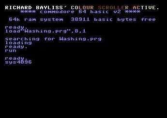
If you take a look at this routine, during the control of the colour washing routine, we take the byte, which is at COLOUR+00 and then we place it at COLOUR+$28, then we call a continuous loop which makes the data table cycle, by subtracting each piece of data in the data table by one, and read the calculations 40 times ($28 times), therefore the data table pulls each byte of data. Also inside our loop, the colours are read from the data table and the positioned on to the C64's colour screen RAM, which is from $D800 until $D828. As for reading the message, you'll see for yourself how that works. It is easy to remember ;o)
There is also a simple way to -reverse- the direction of your colour-washing routine. The listing below shows how you can do this :)
;======================
;COLOUR
WASHING ROUTINE (REVERSED)
;======================
COLWASH
LDA COLOUR+$28
STA COLOUR+$00
LDX #$28
CYCLE
LDA COLOUR-$01,X
STA COLOUR+$00,X
LDA COLOUR,X
STA $D7FF,X
DEX
BNE CYCLE
RTS
We reverse the process. You'll also notice that $D800,x has been changed into $D7FF,x. Why is this? Well, simply because if you used $D800 instead of $D7FF you would find that the C64 will miss the first character, therefore you will need to subtract 1 from the screen ram location. Pretty easy to understand huh?
Something to try:
Now that you have learned how to do simple colour cycling, try and put BOTH routines on to the screen. Create your own message at the top of the screen, and bottom of the screen and use one cycling routine at the top and a reverse routine at the bottom.
There is also a much BETTER way to create a colour flash. Simply by generating a timer, a pointer and a store pointer to place on to the colour RAM. You can then scroll the colours by wrapping the flashing colours over the colour RAM forwards or backwards. The trick can be down like THIS. Simply copy this second example:
!TO "WISHYWASHYV2.PRG",CBM
*=$0810
LDX #$00
SHOWMS LDA MESSAGE,X
STA
$0400,x
STA $0428,X
INX
CPX #MESSAGEEND-MESSAGE
BNE SHOWMS
LDX #<IRQ
LDY #>IRQ
LDA #$00
STX $0314
STY $0315
STA $D012
LDA #$7F
STA $DC0D
LDA #$1B
STA $D011
LDA #$01
STA $D01A
CLI
JMP *
IRQ INC $D019
LDA #$00
STA $D012
JSR FLASH
JMP $EA7E
JSR PAINTLEFT
JSR PAINTRIGHT
LDA FLASHDELAY
CMP #3
BEQ FLASHOK
INC FLASHDELAY
RTS
FLASHOK
LDA #$00
STA FLASHDELAY
LDX FLASHPOINTER
LDA COLOUR,X
STA $D827 ;LAST CHAR ROW 1
STA $D828 ;FIRST CHAR ROW 2
INX
CPX #COLOUREND-COLOUR
BEQ RESETFLASH
INC FLASHPOINTER
RTS
RESETFLASH
LDX #$00
STX FLASHPOINTER
RTS
PAINTLEFT
LDX #$00
PAINTLOOP1
LDA $D801,X
STA $D800,X
INX
CPX #$28
BNE PAINTLOOP1
RTS
PAINTRIGHT
LDX #$27 ;REVERSED!
PAINTLOOP2
LDA $D828,X
STA $D829,X
DEX
BPL PAINTLOOP2
RTS
FLASHDELAY !BYTE 0
FLASHPOINTER !BYTE 0
COLOUR !BYTE $02,$0A,$07,$01,$03,$0E,$06,$09
!CT SCR
MESSAGE !TEXT "two way colour-washing rocks!"
MESSAGEEND
Building
a simple 1x2 scrolling text intro - with a twist
Here is how to code your very own simple 1x2 intro. You should already be familiar with the things this program does. For example how to position text, roll the colours and flash them. The new thing you will learn in this section is how to work a scrolltext, control its speed and also putting the scrolltext inside a raster split (screen cut). After you have played around a lot with the code, why not try and make an intro yourself.
The intro screen isn't much, but here is what it will consist of. Firstly we will clear the whole screen using a control loop, rather than using JSR $E544, we shall also fill two portions of the screen with #$00 for the character code, so that we have some vertical lines; where the colours will pass through. We'll also be flashing the two 1-liner (2-liner text more like) and also add a flashing raster bar (using splits). There's also going to be a 1x2 scrolltext and also some music playing in the background :o))
Before we start, I would like to show you how a 1x2 charset works. A 1x1 charset is 16x16 pixels long. These are formed, somehow like the diagram below
Example of a 1x1 character (We use rvs on as the char pixel)
![]()
As you can see, a 1x1 character works on 8 pixels across to 8 pixels down, but a 1x2 char is different. We use more than 8 pixels down. In fact, we use twice as many pixels, therefore we calculate the area for the 1x2 charset. Considering that the y-axis for a 1x1 charset is half the size of a 1x2 charset, we multiply the y-axis of the 1x1 charset by 2 so, what does 8x2 make? 16 of course. Here's the example below.
Example of a 1x2 character (using rvs on as char pixel).
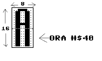
Also, looking at the 1x2 character, when you try to display the character, you will notice that there are two halves of the charset which has to be used. Therefore, if you wanted to display a 1x2 charset you read the line of text from memory twice and paste to the two lines in the screen RAM. However, if you used this method:
LDX #$00
LOOP
LDA MESSAGE,X
STA
(Screenlocation),x
STA
(Screenlocation on next line),x
INX
CPX
#$(How many characters)
BNE
LOOP
This will not work properly, because you are only trying to display a 1x1 charset instead. The proper way is by placing ORA #$40 (or depending on where to put the other half of the character set). You need to place ORA #$40 between after the screen location on first line. Just like the example below.
LDX #$00
LOOP LDA
MESSAGE,x
STA
(Screenlocation),x
ORA #$40
STA
(Screenlocation on next line),x
INX
CPX #$(How
many characters)
BNE LOOP
...and that is the proper way displaying the 1x2 charset. ORA #$40 displays the second half of the charset in memory.
That
is all you really need to learn about displaying a 1x2 charset. You
probably find that displaying 1x2 charsets may be tough at first, but
it is purely simple :o). Take a look at the code, download the data and
source (and tools) and have fun.
RESULT:
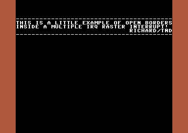
Raster splits cannot just be used for displaying scroll text, synchronizing code, etc. They can also be used for clever tricks. You may discover that some C64 programs can actually open the top and bottom border. Something programs use this method to make sprites visible in those particular areas. How are those opened borders formed? Well, a small routine can simply do the trick, in order to open the top and bottom borders. The trick is basically to grab a raster position from the very bottom, and then trigger the C64's hardware VERTICAL SCREEN POSITION ($D011) to be switched ON. Then call a raster position from the top and switch the vertical screen position on again. The example looks something like this:
Code:
;Opened borders using raster interrupts
;by Richard Bayliss

!to "openborders.prg",cbm ;Generate file

*=$0801
!basic 2018,2064 ;Generate SYS2064

*=$0810
	sei
	lda #$37		;Kernal ROM
	sta $01

	jsr $e544 ;Clear screen

	lda #2				;Red border
	sta $d020
	lda #0				;Black background
	sta $d021

	ldx #$00		;Display text
addtext
	lda message,x
	sta $0400,x
	lda #1
	sta $d800,x
	inx
	cpx #messageend-message
	bne addtext

	ldx #<irq	;Setup IRQ raster interrupt
	ldy #>irq
	stx $0314
	sty $0315
	lda #$7f
	sta $dc0d
	lda #$80
	sta $d012

	lda #$1b
	sta $d011
	lda #$01
	sta $d01a
	cli
	jmp *

irq			;The main IRQ raster interrupt
	inc $d019
	lda #$fa		;Bottom position of raster split
	cmp $d012
	bne *-3
	lda #$00		;Switch screen off in that position
	sta $d011
	lda #$30		;Top position of raster split
	cmp $d012
	bne *-3
	lda #$1b		;Switch screen back on again
	sta $d011
	jmp $ea7e

!ct scr
message
	!text "----------------------------------------"
	!text "this is a little example of open borders"
	!text "inside a multiple irq raster interrupt! "
	!text "                             richard/tnd"
	!text "----------------------------------------"
messageend
Making our first picture demo.
This chapter is
mainly a bit of
theory on how to put everything together and form a demo. Yeah, like it
really is. :D Actually I already done the source code and set up the
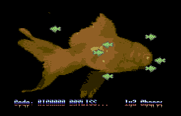
data to produce a simple Goldfish Demo.
What we have
in the demo is a bitmap picture, which was ported into a Koalapaint
format and then split up using the Picture Splitter V2 utility, where
the picture datas get split up and saved to where you wish to place
them in memory. The demo consists of a bitmap picture, some moving
sprites, a scrolltext, and of course some music. The source code was
very old and was done in 2004, but I have updated the source code to
compile into C64Studio.
Let's
give you a quick explanation about how this demo work. First of all,
all of the binary data is imported into the main project. I decided to
use a BIN directory, in order to keep the project in its rightful place.
The charset is placed at $0800. Thus the charset poke command would be POKE 53272,18 - or as we say in assembly LDA #$12 : STA $D018.
A tune is loaded to $1000
The Goldfish sprite is positioned at $1f80 (As there was a little free memory to put the sprites in place)
We set up the picture, simply by reading the memory where it is stored. Which is as follows:
BITMAP $2000-$3f40
COLOUR RAM $4000-$43e8
VIDEO RAM $4400-$47e8
The code starts at $4800.
VIEW SOURCE CODEor alternatively, if you want to try and assemble, run and modify the program
DOWNLOAD C64STUDIO PROJECT + BINARY + SOURCE CODE
Result:
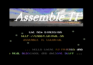
Demo 2 - The Assemble IT Demo
So then, how would you like to try something real fun and exciting. Something very oldschool. In our previous chapter, I talked about using more than one IRQ interrupt. So now, we are going to go even more practical and create a real old school demo, using more than one IRQ raster interrupt. We're even going to use splits to create a couple of scrolltexts. We'll also blend in some effects behind the bitmap, known as a waving effect. Anyway, rather than me type in a load of text, here is what binaries we'll need to use.
* Bitmap/logo (Split into segments - bitmap, videoram, colour ram)
* Sprites (Animated balls borrowed from an Enigma intro)
* 1x1 Charset (Any)
* Music (From HVSC)
* 2 Scroll texts. (Type your own)
Ok. here's the listing below to to get you going with the demo.
VIEW SOURCE CODE
or alternatively
DOWNLOAD C64STUDIO PROJECT SOURCE + BINARY FILES
Earlier
on I showed you some tricks with rasters $D012 (Screen cuts, now we are
going to do something slightly enhanced). I will be showing you an
example of displaying more than just 2 colours. This example displays 3
raster bars of one single colour using a few variables. Each variable
to represent the position of a raster split. Also another variable in
which to represent the colour of each split.
DISPLAYING 3 STATIC COLOUR RASTER SPLITS
!TO "RASTERS2.PRG",CBM
;3 COLOURS INSIDE AN IRQ
RASPOS1 = $3A ;Set raster position (TOP)
RASPOS2 = $9A ;Set raster position (MIDDLE)
RASPOS3 = $DA ;Set raster position (BOTTOM)
RASCOL1 = $06 ;Set raster colour (DARK BLUE)
RASCOL2 = $04 ;Set raster colour (PURPLE/MAGENTA)
RASCOL3 = $0E ;Set raster colour (LIGHT BLUE)
*=$0810
SEI
JSR $E544 ;Just clear the screen
LDA #$37
STA $01
LDA #$00 ;Load Default raster position to A
LDX #<IRQ ;Set IRQ lowbyte to X
LDY #>IRQ ;Set IRQ hibyte to Y
STA $D012 ;Store raster position
STX $0314 ;Store IRQ vector low X
STY $0315 ;Store IRQ vector hi Y
LDA #$7F
STA $DC0D ;Enable CIA
LDA #$1B
STA $D011 ;Screen On
LDA #$01
STA $D01A ;ACK IRQ interrupt flag
CLI
JMP *
IRQ
INC $D019
LDA $DC0D ;Copy CIA to next CIA
STA $DD0D
JSR RASTERS ;Call subroutine to display rasters
JMP $EA7E ;IRQ interrupt loop
;Setup and display rasters
RASTERS
LDA #RASPOS1 ;Load value/variable raster position 1
CMP $D012 ;Compare to current raster position
BNE *-3
LDA #RASCOL1 ;Load value/variable raster colour
STA $D020 ;Store to border + background
STA $D021
LDA #RASPOS2 ;Load next value/variable raster position 2
CMP $D012 ;Compare to current raster position
BNE *-3
LDA #RASCOL2 ;Load value/variable of raster colour 2
STA $D020 ;Store to border + background
STA $D021
LDA #RASPOS3 ;Load value/variable of raster position 3
CMP $D012 ;Compare to current raster position
BNE *-3
LDA #RASCOL3 ;Load value/variable of raster colour 3
STA $D020 ;Store to border + background
STA $D021
RTS
RESULT:

LDX #TIMING_AMOUNT
DEX
BNE *-1
RASTERS WITH TIMING (SINGLE TIMING PER RASTER LINE)
;TO "RASTERS3.PRG",CBM
;3 COLOURS INSIDE AN IRQ
RASPOS1 = $3A ;Set raster position (TOP)
RASPOS2 = $9A ;Set raster position (MIDDLE)
RASPOS3 = $DA ;Set raster position (BOTTOM)
RASCOL1 = $06 ;Set raster colour (DARK BLUE)
RASCOL2 = $04 ;Set raster colour (PURPLE/MAGENTA)
RASCOL3 = $0E ;Set raster colour (LIGHT BLUE)
*=$0810
SEI
JSR $E544 ;Just clear the screen
LDA #$37
STA $01
LDA #$00 ;Load Default raster position to A
LDX #<IRQ ;Set IRQ lowbyte to X
LDY #>IRQ ;Set IRQ hibyte to Y
STA $D012 ;Store raster position
STX $0314 ;Store IRQ vector low X
STY $0315 ;Store IRQ vector hi Y
LDA #$7F
STA $DC0D ;Enable CIA
LDA #$1B
STA $D011 ;Screen On
LDA #$01
STA $D01A ;ACK IRQ interrupt flag
CLI
JMP *
IRQ
INC $D019
LDA $DC0D ;Copy CIA to next CIA
STA $DD0D
JSR RASTERS ;Call subroutine to display rasters
JMP $EA7E ;IRQ interrupt loop
;Setup and display rasters
RASTERS
LDA #RASPOS1 ;Load value/variable raster position 1
CMP $D012 ;Compare to current raster position
BNE *-3
LDX #$0A ;Timing value (May vary)
DEX
BNE *-1
LDA #RASCOL1 ;Load value/variable raster colour
STA $D020 ;Store to border + background
STA $D021
LDA #RASPOS2 ;Load next value/variable raster position 2
CMP $D012 ;Compare to current raster position
BNE *-3
LDX #$0A ;Timing value (May vary)
DEX
BNE *-1
LDA #RASCOL2 ;Load value/variable of raster colour 2
STA $D020 ;Store to border + background
STA $D021
LDA #RASPOS3 ;Load value/variable of raster position 3
CMP $D012 ;Compare to current raster position
BNE *-3
LDX #$0A ;Timing value (May vary)
DEX
BNE *-1
LDA #RASCOL3 ;Load value/variable of raster colour 3
STA $D020 ;Store to border + background
STA $D021
RTS
The splits are then straightened up nicely. Depending on the raster line, which you are using you will need to try and time out each raster.
BACK TO TOP
DISPLAYING RASTER BARS USING A TIMING TABLE
So far, we have learned how to display some 3 big colour splits. It is possible to add more than 3 colour splits, but I will leave you to try that with your capable hands. Now, we are going to do something fun and practical - before coding a fun little intro with some of the things that we already learned so far in this chapter. Of course you won't be able to display scroll text yet that will happen eventually.
In this example I am going to show you how to display raster colour bars, with aid of a timing table. After that, we are going to have some fun at making a little intro in ACME/C64Studio.
!to "rasters4.prg",cbm
;Displaying raster splits using Colour and timing tables
;The old 8 raster bars trick
*=$0810 ;SYS2064
SEI
LDA #$37
STA $01
JSR $E544 ;CLEAR SCREEN FOR FUN
LDA #$00
LDX #<IRQ
LDY #>IRQ
STX $0314
STY $0315
STA $D012
LDA #$7F
STA $DC0D
LDA #$1B
STA $D011
LDA #$01
STA $D01A
CLI
JMP *
IRQ
INC $D019
LDA $DC0D
STA $DD0D
JSR RASTERBAR
JMP $EA7E
RASTERBAR
LDA #$3A ;Set position of raster split
CMP $D012 ;to current raster position.
BNE *-3
LDX #$00
RASTERLOOP
LDA RASCOL,X
LDY TIMING,X
DEY
BNE *-1
STA $D020
STA $D021
INX
CPX #TIMINGEND-TIMING ;Or you could use RASCOLEND-RASCOL
BNE RASTERLOOP
RTS
;Table for raster colours
RASCOL !byte $02,$0a,$07,$01,$03,$0e,$06,$00
RASCOLEND !byte $00
;Table for raster timing (requires patience with flicker fixing)
;NOTE: In order to work out the timing for each raster line,
;you need to trigger a flicker to move left / right on current line
;according to the value of the raster position. This requires a lot
;of trial and error. It is very easy to time out each line, but
;can be a real pain now and then anyhow :)
TIMING !byte $09,$01,$08,$08,$08,$08,$08,$08
TIMINGEND !byte $00
RESULT:

Want to add another bar? Let's extend the code:
;Displaying raster splits using Colour and timing tables
;The old 8 raster bars trick
;TO "RASTERS5.PRG",CBM
*=$0810 ;SYS2064
SEI
LDA #$37
STA $01
JSR $E544 ;CLEAR SCREEN FOR FUN
LDA #$00
LDX #<IRQ
LDY #>IRQ
STX $0314
STY $0315
STA $D012
LDA #$7F
STA $DC0D
LDA #$1B
STA $D011
LDA #$01
STA $D01A
CLI
JMP *
IRQ
INC $D019
LDA $DC0D
STA $DD0D
JSR RASTERBAR
JMP $EA7E
RASTERBAR
LDA #$3A ;Set position of raster split
CMP $D012 ;to current raster position.
BNE *-3
LDX #$00
RASTERLOOP
LDA RASCOL,X
LDY TIMING,X
DEY
BNE *-1
STA $D020
STA $D021
INX
CPX #TIMINGEND-TIMING ;Or you could use RASCOLEND-RASCOL
BNE RASTERLOOP
LDA #$7A ;Set position of raster split 2
CMP $D012 ;to current raster position
BNE *-3
LDX #$00
RASTERLOOP2
LDA RASCOL2,x
LDY TIMING2,X
DEY
BNE *-1
STA $D020
STA $D021
INX
CPX #TIMING2END-TIMING2
BNE RASTERLOOP2
RTS
;Table for raster colours
RASCOL !byte $02,$0a,$07,$01,$03,$0e,$06,$00
RASCOLEND !byte $00
RASCOL2 !byte $06,$0e,$03,$01,$07,$0a,$02,$09
RASCOL2END
;Table for raster timing (requires patience with flicker fixing)
;NOTE: In order to work out the timing for each raster line,
;you need to trigger a flicker to move left / right on current line
;according to the value of the raster position. This requires a lot
;of trial and error. It is very easy to time out each line, but
;can be a real pain now and then anyhow :)
TIMING !byte $09,$01,$08,$08,$08,$08,$08,$08
TIMINGEND !byte $00
TIMING2 !byte $09,$01,$08,$08,$08,$08,$08,$08
TIMING2END !byte $00
RESULT:

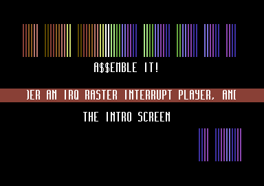
Now that looks really nice. The next part of this chapter is going to show you a basic example of creating a simple little intro, with a simple PETSCII coded logo placed inside the raster split. All you need to do is use C64Studio to design your own logo. Then export the logo as data. It will also be nice to add some sound to the little intro as well. I name this example.
How does a timing table work?
Depending on the position of a raster, the method I showed above depends on the raster position. Moving a flicker of a raster position forward (or backwards) will depend on the value of the timing table. To get a 100% working raster line, takes a little time and precision.
BACK TO TOP
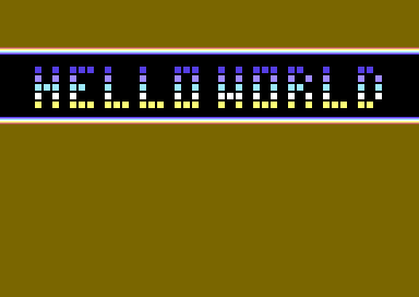
HELLO WORLD #2
In this little example, we are going to add what we have learned so far. Basically, using the same example from above, we are going to add a HELLO WORLD logo on to the screen. Using C64Studio, create and design your logo using the screen editor, and create your logo as 6 characters height by 40 characters width. Then save and export your logo as a binary file or as assembly data. We are going to draw a matrix, and also flash the colours upwards, by scrolling a row from the colour RAM to the next row. Here is the example code. I have also uploaded the C64Studio binary and source, which you can download from this page, by clicking on the picture below.
!to "helloworld2.prg",cbm
MUSICINIT = $1000
MUSICPLAY = $1003
;Displaying raster splits using Colour and timing tables
;The old 8 raster bars trick
*=$0810 ;SYS2064
SEI
LDA #$37
STA $01
JSR $E544 ;CLEAR SCREEN FOR FUN
;Draw the HELLO WORLD PETSCII logo
;to the third raster line.
LDX #$00
DRAWMATRIX
LDA MATRIX,X
STA $0478,X ;TIP: You can draw $0478,x as $0400+120,x or $0400+3*40,x
LDA #1
STA $D878,X
INX
CPX #6*40 ;Total Number of rows, the matrix is set! (Or we say 240)
BNE DRAWMATRIX
LDA #$00
LDX #<IRQ
LDY #>IRQ
STX $0314
STY $0315
STA $D012
LDA #$7F
STA $DC0D
LDA #$1B
STA $D011
LDA #$01
STA $D01A
LDA #$00
JSR MUSICINIT
CLI
JMP *
IRQ
INC $D019
LDA $DC0D
STA $DD0D
JSR MUSICPLAY
JSR FLASHCOLOURS
JSR RASTERBAR
JMP $EA7E
FLASHCOLOURS
LDA FLASHDELAY
CMP #$03 ;Delay long enough?
BEQ FLASHOK
INC FLASHDELAY ;Increment flash delay
RTS
FLASHOK
JSR PAINT ;Store colours to text.
LDA #$00 ;Reset delay of flash
STA FLASHDELAY
LDX FLASHPOINTER
LDA FLASHTABLE,X
STA FLASHSTORE
INX
CPX #FLASHTABLEEND-FLASHTABLE
BEQ RESETFLASH
INC FLASHPOINTER
RTS
RESETFLASH
LDX #$00 ;Reset/loop flashing colour
STX FLASHPOINTER
RTS
;Paint flashing text to screen colour RAM (bottom line)
;the idea will be to make the colours fade upwards.
PAINT
LDX #$00
DOPAINT
LDA $D8A0,X
STA $D878,X
LDA $D8C8,X
STA $D8A0,X
LDA $D8F0,X
STA $D8C8,X
LDA $D918,X
STA $D8F0,X
LDA $D940,X
STA $D918,X
LDA $D968,X
STA $D940,X
LDA FLASHSTORE
STA $D968,X
INX
CPX #$28 ;OR #40 CHARS
BNE DOPAINT
RTS
RASTERBAR
LDA #$3A ;Set position of raster split
CMP $D012 ;to current raster position.
BNE *-3
LDX #$00
RASTERLOOP
LDA RASCOL,X
LDY TIMING,X
DEY
BNE *-1
STA $D020
STA $D021
INX
CPX #TIMINGEND-TIMING ;Or you could use RASCOLEND-RASCOL
BNE RASTERLOOP
LDA #$7A ;Set position of raster split 2
CMP $D012 ;to current raster position
BNE *-3
LDX #$00
RASTERLOOP2
LDA RASCOL2,x
LDY TIMING2,X
DEY
BNE *-1
STA $D020
STA $D021
INX
CPX #TIMING2END-TIMING2
BNE RASTERLOOP2
RTS
;Pointers for colour flashing
FLASHDELAY !BYTE 0
FLASHPOINTER !BYTE 0
FLASHSTORE !BYTE 0
;Table for flashing colours
FLASHTABLE !byte $00,$02,$0a,$07,$01,$03,$0e,$06,$00,$06
!byte $0e,$03,$01,$07,$0a,$02
FLASHTABLEEND
;Table for raster colours
RASCOL !byte $02,$0a,$07,$01,$03,$0e,$06,$00
RASCOLEND !byte $00
RASCOL2 !byte $06,$0e,$03,$01,$07,$0a,$02,$09
RASCOL2END
;Table for raster timing (requires patience with flicker fixing)
;NOTE: In order to work out the timing for each raster line,
;you need to trigger a flicker to move left / right on current line
;according to the value of the raster position. This requires a lot
;of trial and error. It is very easy to time out each line, but
;can be a real pain now and then anyhow :)
TIMING !byte $09,$01,$08,$08,$08,$08,$08,$08
TIMINGEND !byte $00
TIMING2 !byte $09,$01,$08,$08,$08,$08,$08,$08
TIMING2END !byte $00
;Add some music (PICK A TUNE OF YOUR OWN CHOICE)
*=$1000
!BIN "ZAPFIGHT2INTRO.PRG",,2
;HELLO WORLD logo matrix/screen (Size has been cut down, since too much wasted bytes)
*=$2000
MATRIX
!BIN "HWLOGO.BIN"
MATRIXEND
RESULT:
CHALLENGE #1:
Now you have learned a little about raster splits and screen position. I have a set challenge for you to try. Following the example we have just done. Try and create a couple of extra raster splits with colour bars and time them out. Then add the HELLO WORLD at the BOTTOM of the screen with colour roll going the opposite direction, compared to the logo at the top. Hint: This can easily be done by putting a low raster split. Re-reading the same colour table. and repeating the previous code - However, you may need to work on timing out the rasters with timing tables.
CREATING EVEN MORE RASTER BARS WITH TIMING
This can be done the same way as above. However you MUST be careful where to put your raster split, because raster splits have their own limitation. A raster must NOT overlap another raster, otherwise it will cause the program to flicker and slow down in a nasty way. In order to prevent this from happening. You should avoid using TOO much raster time and OVERLAPPING a raster position.
Anyway, why don't we create a new program that will display MORE raster bars, using timing and colour tables. Try this first!!!
;Displaying multiple raster bars by Richard/TND
!TO "MULTIRASTERS.PRG",CBM
*=$0810 ;SYS2064
SEI
JSR $E544 ;Quick screen clear as usual
LDA #$00
LDX #<IRQ
LDY #>IRQ
STX $0314
STY $0315
STA $D012
LDA #$7F
STA $DC0D
LDA #$1B
STA $D011
LDA #$01
STA $D01A
CLI
JMP *
IRQ
INC $D019
LDA $DC0D
STA $DD0D
JSR RASTERS
JMP $EA7E
;Rasters
LDA #$3A ;Top raster position
CMP $D012
BNE *-3
;Just for fun, let's display 64 raster bars
RASTERS
LDX #$00
RASLOOP
LDA COLOURTABLE,X ;Read colour table
LDY TIMINGTABLE,X ;Read raster timing tables
DEY
BNE *-1
STA $D020 ;Inside raster split display colour
STA $D021 ;bars.
INX
CPX #COLOURTABLEEND-COLOURTABLE
BNE RASLOOP
RTS
;Now set up the tables to display the raster colours (64 OF THEM)
COLOURTABLE
!BYTE $06,$0E,$03,$01,$03,$0E,$06,$00 ;8 - BLUE
!BYTE $02,$0A,$07,$01,$07,$0A,$02,$00 ;16 -RED
!BYTE $0B,$0C,$0F,$01,$0F,$0C,$0B,$00 ;24 -SILVER
!BYTE $09,$08,$07,$01,$07,$08,$09,$00 ;32 -GOLD
!BYTE $05,$03,$0D,$01,$0D,$03,$05,$00 ;40 -GREEN
!BYTE $06,$04,$0E,$01,$0E,$04,$06,$00 ;48 -PURPLE
!BYTE $08,$0A,$0F,$01,$0F,$0A,$08,$00 ;56 -ORANGE
!BYTE $02,$04,$0A,$01,$0A,$04,$02,$00 ;64 -RED / PURPLE
COLOURTABLEEND
!BYTE $00
;Timing table for the raster colour bars (64 of them)
TIMINGTABLE
!BYTE $09,$01,$08,$08,$08,$08,$08,$08
!BYTE $09,$01,$08,$08,$08,$08,$08,$08
!BYTE $09,$01,$08,$08,$08,$08,$08,$08
!BYTE $09,$01,$08,$08,$08,$08,$08,$08
!BYTE $09,$01,$08,$08,$08,$08,$08,$08
!BYTE $09,$01,$08,$08,$08,$08,$08,$08
!BYTE $09,$01,$08,$08,$08,$08,$08,$08
!BYTE $09,$01,$08,$08,$08,$08,$08,$08
TIMINGTABLEEND
!BYTE $00
RESULT:
So what happened here? Although we are displaying rasters on screen, they seem to be BADLY timed out and untidy.Also the initialised raster before the interrupt starts is in the incorrect position. Therefore we cannot see ALL of the colour bars that were set out on the table/ So what needs to be done is a slight adjustment to the raster split display code. Also a small trial + error trick, for raster timing. We need to manually move the flickering forward/backward a certain number of steps by altering each byte on the raster timing table. The way to fix it is by the watching the flicker from the top rasterline, to the bottom raster line. This may be quite time consuming, but you will get a positive result at the end if done properly.
Here is one solution I have come up with. The initialised raster starts at line #$32 (Which is 64 in decimal). An interrupt is called and then the bars are then displayed on screen. However, the timing table had to be adjusted in order to have a flicker-free display of raster bars. Here is the code in full:
;Displaying multiple raster bars with better timing by Richard/TND
!TO "MULTIRASTERS2.PRG",CBM
*=$0801
!basic 2018,$0810
*=$0810 ;SYS2064
SEI
JSR $E544 ;Quick screen clear as usual
LDA #$32
LDX #<IRQ
LDY #>IRQ
STX $0314
STY $0315
STA $D012
LDA #$7F
STA $DC0D
LDA #$1B
STA $D011
LDA #$01
STA $D01A
CLI
JMP *
IRQ
INC $D019
LDA $DC0D
STA $DD0D
JSR RASTERS
JMP $EA7E
;Rasters
LDA #$3a ;Top raster position
CMP $D012
BNE *-3
;Just for fun, let's display 64 raster bars
RASTERS
LDX #$00
RASLOOP
LDA COLOURTABLE,X ;Read colour table
LDY TIMINGTABLE,X ;Read raster timing tables
DEY
BNE *-1
STA $D020 ;Inside raster split display colour
STA $D021 ;bars.
INX
CPX #COLOURTABLEEND-COLOURTABLE
BNE RASLOOP
LDA #$00
STA $D020
STA $D021
RTS
;Now set up the tables to display the raster colours (64 OF THEM)
COLOURTABLE
!BYTE $06,$0E,$03,$01,$03,$0E,$06,$00 ;8 - BLUE
!BYTE $02,$0A,$07,$01,$07,$0A,$02,$00 ;16 -RED
!BYTE $0B,$0C,$0F,$01,$0F,$0C,$0B,$00 ;24 -SILVER
!BYTE $09,$08,$07,$01,$07,$08,$09,$00 ;32 -GOLD
!BYTE $05,$03,$0D,$01,$0D,$03,$05,$00 ;40 -GREEN
!BYTE $06,$04,$0E,$01,$0E,$04,$06,$00 ;48 -PURPLE
!BYTE $08,$0A,$0F,$01,$0F,$0A,$08,$00 ;56 -ORANGE
!BYTE $02,$04,$0A,$01,$0A,$04,$02,$00 ;64 -RED / PURPLE
COLOURTABLEEND
!BYTE $00
;Timing table for the raster colour bars (64 of them)
TIMINGTABLE
!BYTE $04,$08,$08,$08,$08,$08,$08,$08
!BYTE $01,$08,$08,$08,$08,$08,$08,$08
!BYTE $01,$08,$08,$08,$08,$08,$08,$08
!BYTE $01,$08,$08,$08,$08,$08,$08,$08
!BYTE $01,$08,$08,$08,$08,$08,$08,$08
!BYTE $01,$08,$08,$08,$08,$08,$08,$08
!BYTE $01,$08,$08,$08,$08,$08,$08,$08
!BYTE $01,$08,$08,$08,$08,$08,$08,$09
TIMINGTABLEEND
!BYTE $00
RESULT:

There much better. Also, did you know that you can also add rasters with timing to other features, such as using charset multicolour inside a standard or scrolling screen, making waving text, etc. These are all made by using raster splits with timing tables or dummy timing tables. However, you might want to know how to move the colour bars? Well, there are different ways in which this can be done. You can call a subroutine which will roll data table forward or call a subroutine which will roll the data table backward. Here is how it is usually done (This is not the full code, but just a little example, since the full code will be on the intro making part of this section.
Rolling full 64 bars upwards:
LDA COLOURTABLE
STA $02
LDX #$00
SCROLLUP
LDA COLOURTABLE+1,X
STA COLOURTABLE+0,X
INX
CPX #64
BNE SCROLLUP
LDA $02
STA COLOURTABLEEND
RTS
So then what will this routine above do? It fetches the very first byte of the colour table. Store it to a zeropage ($02). Then call a loop in which pulls up to 64 bytes of the colour table backwards. After one cycle of the colour table movement. The subroutine will then plant the stored byte from the zeropage ($02) and place it as the very last byte in the colour table. The colours will then repeat themselves scrolling upwards.
What about if you wanter roll the 64 bars downwards? Well, it is a completely different kettle of fish. Basically you can reverse the process. Here's how:
Rolling full 64 bars downwards:
LDA COLOURTABLEEND
STA $02
LDX #63
SCROLLDOWN
LDA COLOURTABLE-1,X
STA COLOURTABLE+0,X
DEX
BPL SCROLLDOWN
LDA $02
STA COLOURTABLE
RTS
Of course as tempbytes (Where I used zeropage $02), you don't have to use $02. You can use any other tempbyte, as long as it is NOT being used for any other purpose inside your code. Otherwise strange results will happen.
CHALLENGE #2
Before we make a simple noisey intro, using rasterbars, logo and scrolltext. Using the example routine and implementing the rolling bars routine. Create and display a logo (As in the previous challenge), as the first 6 or 7 chars and try to make it wobble, by replacing the colour table with the $D016 wobbling values $10-$17 and change the border colour settings to $D016, to see what will happen.
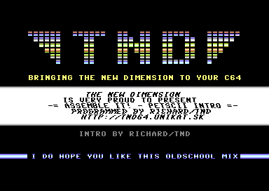
INTRO #2 - OLDSCHOOL INTRO
In this part of the chapter. We are going to be creating a simple Oldschool Intro, using C64Studio. From the things you have learned so far. Here's what we are going to do. This is NOT going to be one of those really exciting intros. Just a simple PETSCII intro, as you would have expected to have seen from one of those old cracktros back in the late 1980's/Early 1990's. This intro is to display a logo and play some music, as we did with HELLO WORLD. However, it will also show you how to display a 1x1 smooth scrolling text while still at it and use some flashing. Before we go on to the main code. A quick bit of information:
Yet again the amount of rasters for the top part of the screen, uses 64 raster bars. The table for the colour scroll at the top of the raster is split into 32 bytes. Same also for the bottom. The colour rolling has been set as a background colour. The logo was drawing in C64Studio is using a PETSCII logo, made from the standard C64 PETSCII using the RVS ON character set.
The raster bar in the middle has been split into 3 different rasters. The top part of the screen uses 4 raster colours, also with a timing table. Then the central part uses plain white border+background colour, and triggers a wobble effect, the same way as a colour effect would take place. A table is read and cycled in order to trigger the wobbling effect of the black text inside the raster. After reaching the end of the raster. Static text is set, followed by another raster bar with 4 colours and 4 bytes of timing.
The bottom screen triggers the smooth scroll pointer first (Which was originally called from the SCROLLINGTEXT subroutine. It basically subtracts a value of the horizontal screen position, but can only use values 0 to 8 in order to perform a smooth scrolling operation. The scroll pointer is then stored to the hardware Horizontal Screen Position ($D016). There is also another 8 bytes of colour added to the border and background colour, with another 8 bytes timing the table out. There you have it. A fully working intro.
Here comes the code, which is quite self-explanatory:
;Assemble It - Intro 2
;Basic PETSCII Oldschool with rasters
;By Richard Bayliss
!to "AssembleItPetsciiIntro.prg",cbm
;Some zeropage variables for raster control
RASDELAY = $02 ;Moving bars delay subroutine
RASTEMP1 = $03 ;Temp storebyte for picking next upscrolling raster
RASTEMP2 = $04 ;Temp storebyte for picking next downscroll raster
SHKDELAY = $05 ;Text shaking delay subroutine
SHKTEMP = $06 ;As with RASTEMP, temp storebyte for picking next shake byte
XPOS = $07 ;Smooth scroll indicator
MUSICINIT = MUSICPLAYER
MUSICPLAY = MUSICPLAYER+3
*=$0801
!BASIC 2018,2064 ;SYS2064
*=$0810
SEI
;Full screen / char clear (Much better)
;using spacebar char
;Initialise all zeropages. This is so that all delay pointers
;are set to the correct time/duration.
LDA #0
STA RASDELAY
STA RASTEMP1
STA RASTEMP2
STA SHKDELAY
STA SHKTEMP
STA XPOS
LDX #$00
FULLCLEAR
LDA #$20 ;(Or 32, - the value of space bar character)
STA $0400,X
STA $0500,X
STA $0600,X
STA $06E8,X
STA $D800,X
STA $D900,X
STA $DA00,X
STA $DAE8,X
INX
BNE FULLCLEAR
;Draw simple PETSCII logo to the top area of the screen
;so that it fits the 64 raster bars, we want to use for
;the raster PETSCII intro. The code below will pick up
;the actual logo and paste it on to the the screen.
LDX #$00
DRAWLOGO
;Logo matrix to screen
LDA MATRIX,X
STA $0400,X
LDA MATRIX+40,X
STA $0400+40,X
LDA MATRIX+80,X
STA $0400+80,X
LDA MATRIX+120,X
STA $0400+120,X
LDA MATRIX+160,X
STA $0400+160,X
LDA MATRIX+200,X
STA $0400+200,X
LDA MATRIX+240,X
STA $0400+240,X
LDA #$A0
STA $0400+280,X
STA $0400+320,X
INX
CPX #$28 ;(Or #40 columns)
BNE DRAWLOGO
;Initialise scroll text:
LDA #<SCROLLTEXT
STA MESSREAD+1
LDA #>SCROLLTEXT
STA MESSREAD+2
;Now place presentation text on to the central area of
;the screen.
LDX #$00
PLACETEXT
LDA LINETEXT,X ;Text to be read
STA $05E0,X ;Text to be placed on to screen
INX
CPX #LINETEXTEND-LINETEXT ;Get overall length of text. Only if < 256 chars
BNE PLACETEXT
;Then place the second presentation text (Slogan) in to the bottom area of the
;screen. - Paint it white!
LDX #$00
PLACETEXT2
LDA LINETEXT2,X
STA $0568,X
LDA LINETEXT3,X
STA $06F8,X
INX
CPX #LINETEXT2END-LINETEXT2
BNE PLACETEXT2
;Initialise interrupts, and place raster split in a position
;it should initialise at
LDA #$32 ;Raster position
LDX #<IRQ ;Interrupt lo-byte
LDY #>IRQ ;Interrupt hi-byte
STX $0314
STY $0315
STA $D012
LDA #$7F ;Setup CIA chip to enable interrupt
STA $DC0D
LDA #$1B ;Whole code for intro can use standard
STA $D011 ;char vertical screen position
LDA #$01
STA $D01A ;Allow interrupt to delay slightly (SYNC)
LDA #$00
JSR MUSICINIT ;Initialise music
CLI
JMP * ;Allow the code to just jump to itself, since
;the IRQ interrupt code will do the rest.
IRQ
INC $D019 ;Allow interrupt to delay slightly (As with $d01A)
LDA $DC0D ;Stabilize the CIA so that every restart of the
STA $DD0D ;intro, after loading it nothing weird happens.
JSR SCROLLTOPRASTER ;Subroutine for scrolling the top raster bar
JSR WOBBLETEXT ;Subroutine to wobble the text
JSR SCROLLINGTEXT ;Do scrolling text subroutine
JSR SPACEBARPROMPT ;As always an intro should have a spacebar prompt
JSR RASTERS ;Subroutine to produce rasters (with timing)
JSR MUSICPLAY ;Play Richard's music
JMP $EA7E
RASTERS
LDA #$3A
CMP $D012
BNE *-3
LDA #8 ;No scrolling or wobbling text.
STA $D016
LDX #$00
DRAWCOLOURS
LDY TIMINGTABLE1,X
DEY
BNE *-1
LDA RASTERBARS1,X
;STA $D020
STA $D021
INX
CPX #RASTERBARS1END-RASTERBARS1;Total number of raster lines to read
BNE DRAWCOLOURS
LDA #0
STA $D020
STA $D021
;Draw the next rasterbar, opening before the text wobbler
;is in place
LDA #$8A
CMP $D012
BNE *-3
LDX #$00
DRAWCOLOURS2
LDY TIMINGTABLE2,X
DEY
BNE *-1
LDA RASTERBARS2,X
STA $D020
STA $D021
INX
CPX #4
BNE DRAWCOLOURS2
;Next raster to use the text shaker code
LDA #$92
CMP $D012
BNE *-3
LDX #$00
DRAWWOBBLER
LDY TIMINGTABLE3,X
DEY
BNE *-1
LDA SHAKETABLE,X
STA $D016
INX
CPX #SHAKETABLEEND-SHAKETABLE
BNE DRAWWOBBLER
;Draw the closing rasterbar, after the wobbling text
LDA #$BE
CMP $D012
BNE *-3
LDX #$00
DRAWCOLOURS3
LDY TIMINGTABLE4,X
DEY
BNE *-1
LDA RASTERBARS3,X
STA $D020
STA $D021
INX
CPX #4
BNE DRAWCOLOURS3
LDX #$08 ;Time it out a little more
DEX
BNE *-1
LDA #0
STA $D020
STA $D021
LDA #$08 ;Stop wave table from being read
STA $D016
;Set bottom raster, for 1x1 smooth scroll text (Including
;colour bars).
LDA #$EA
CMP $D012
BNE *-3
LDA XPOS ;Scroll control byte for scroll text
STA $D016
LDX #$00
DRAWCOLOURS4
LDY TIMINGTABLE5,X
DEY
BNE *-1
LDA RASTERBARS4,X
STA $D020
STA $D021
INX
CPX #RASTERBARS4END-RASTERBARS4
BNE DRAWCOLOURS4
LDA #0
STA $D020
STA $D021
RTS
;Scroll the top raster (Using a delay). We split the
;colour data in half, where the top half of the screen
;rolls upwards. Also the bottom half of the screen
;rolls downwards.
SCROLLTOPRASTER
LDA RASDELAY
CMP #3 ;Maximum speed reached for scrolling?
BEQ DORASSCROL ;YES do raster scroll
INC RASDELAY ;Otherwise increment one byte for the
;Raster delay.
RTS
;Call a couple of subroutines for raster scrolling.
DORASSCROL
LDA #0
STA RASDELAY
JSR SCROLLBARUP ;Subr. scroll raster bars up
JSR SCROLLBARDOWN ;Subr. scroll raster bars down
JSR FLASHTEXT
RTS
;Scroll the first half of the top raster split (32 bytes)
;upwards. So that the colour is cycling.
SCROLLBARUP
LDA COLOURTABLE1
STA RASTEMP1
LDX #$00
SHIFTUP
LDA COLOURTABLE1+1,X
STA COLOURTABLE1,X
INX
CPX #COLOURTABLE1END-COLOURTABLE1
BNE SHIFTUP
LDA RASTEMP1
STA COLOURTABLE1
RTS
;Now scroll the bottom half of the top raster split
SCROLLBARDOWN
LDA COLOURTABLE2END
STA RASTEMP2
LDX #COLOURTABLE2END-COLOURTABLE2
SHIFTDOWN
LDA COLOURTABLE2-1,X
STA COLOURTABLE2,X
DEX
BNE SHIFTDOWN
LDA RASTEMP2
STA COLOURTABLE2
RTS
;Wobble the text, which is inside the white raster bar
WOBBLETEXT
LDA SHKDELAY ;Delay the speed of the shaking subroutine
CMP #$01
BEQ DOSHAKE
INC SHKDELAY
RTS
DOSHAKE
LDA #$00
STA SHKDELAY
LDA SHAKETABLE ;Just like we have done before
STA SHKTEMP ;take the first byte of the table then store it to zp
LDX #$00
DOWOBBLE
LDA SHAKETABLE+1,X
STA SHAKETABLE,X
INX
CPX #SHAKETABLEEND-SHAKETABLE ;Length of shaketable
BNE DOWOBBLE
LDA SHKTEMP ;Fetch last byte stored to SHKTEMP and store
STA SHAKETABLEEND-1 ;to last byte of the shake table
RTS
;Flash some text, simply by reading a byte from the colour bars and then
;store to the presentation text.
FLASHTEXT
LDX #$00
FLASHLOOP
LDA COLOURTABLE2
STA $D968,X
LDA COLOURTABLE2+16
STA $DAF8,X
INX
CPX #40
BNE FLASHLOOP
RTS
;Scrolling text subroutine
SCROLLINGTEXT
LDA XPOS
SEC
SBC #2 ;Speed of scroll
AND #7 ;Only values 0-7 allowed to be used for softscroll+delay
STA XPOS
BCS ENDSCROLL
LDX #$00
SHIFT LDA $0799,X
STA $0798,X
INX
CPX #$28
BNE SHIFT
MESSREAD
LDA SCROLLTEXT
CMP #$00 ;@ character spotted (BYTE $00)
BNE STORECHAR ;No, just store character
;Restart the message (Since @ is spotted)
LDA #<SCROLLTEXT
STA MESSREAD+1
LDA #>SCROLLTEXT
STA MESSREAD+2
JMP MESSREAD
STORECHAR
EOR #$80 ;Invert charset
STA $0798+39 ;Store to the next char for message
INC MESSREAD+1 ;Self-mod message reading, next lowbyte
BNE ENDSCROLL
INC MESSREAD+2 ;next hi-byte
ENDSCROLL
RTS
;Setup and allow the space bar to be pressed in order
;to exit the intro and run a code reloc/transfer subroutine
SPACEBARPROMPT
LDA $DC01
CMP #$EF
BNE NOSPACEBARPRESSED
JMP EXITINTRO
NOSPACEBARPRESSED
RTS
;Intro exit ... Kill all interrupts and disable CIA
;and prepare code transfer/relocation subroutine.
EXITINTRO
SEI
LDX #<$EA31
LDY #>$EA31
LDA #$81
STX $0314
STY $0315
STA $DC0D
STA $DD0D
LDA #$00
STA $D019
STA $D01A
;Initialise SID chip (Kill sound)
LDX #$00
KILLSOUND
LDA #$00
STA $D400,X
INX
CPX #$18
BNE KILLSOUND
;Soft screen init
JSR $FF81 ;Blue border+blue screen clear
;Now select an unused address for placing a program
;transfer/relocation subroutine
LDX #$00
PUTTRANSFER
LDA TRANSFER,X
STA $0100,X
INX
BNE PUTTRANSFER
CLI
JMP $0100 ;Jump to SM transfer routine
;The main code transfer subroutine, which will move
;data from one specific address to another memory
;location.
TRANSFER
SEI
LDA #$34 ;Use all ROMs ($0800-$FFFF) for
STA $01 ;relocation of LARGE files.
TRANSLOOP1
LDX #$00
TRANSLOOP2
LDA PROGRAMLINKADDR,X ;Fetch link address of main program
STA $0801,X ;Store to BASIC pointer
INX
BNE TRANSLOOP2
INC $0109 ;Self-mod address for shifting lo byte of address
INC $010C ;Self-mod address for shifting hi byte of address
LDA $0109 ;Have we reached past $FFFF?
BNE TRANSLOOP1 ;Continue relocation subroutine
LDA #$37 ;Otherwise restore KERNAL vectors
STA $01
CLI
JSR $A659 ;BASIC RUN:
JMP $A7AE ;
TRANSFEREND
;Import music into $1000, before adding raster bars to
;the mix.
*=$1000
MUSICPLAYER
!BIN "MUSIC.PRG",,2
!ALIGN $20,$00
!CT SCR
;JUST A LITTLE INFO TEXT
!TEXT "definitely not future composer by richard/tnd"
;Setup the raster colours and timing tables for
;the raster splits, where the logo lies.
;The colour bars that will appear at the
;top half of the screen (64 lines in total).
RASTERBARS1
COLOURTABLE1
!BYTE $06,$0e,$03,$01,$03,$0e,$06 ;8 - Blue
!BYTE $0b,$0c,$0f,$01,$0f,$0c,$0b ;16 - Silver
!BYTE $09,$05,$0d,$01,$0d,$05,$09 ;24 - Green
!BYTE $02,$0a,$07,$01,$07,$0a,$02 ;32 - Red
COLOURTABLE1END
COLOURTABLE2
!BYTE $02,$0a,$07,$01,$07,$0a,$02 ;8 - Red
!BYTE $09,$05,$0d,$01,$0d,$05,$09 ;16 - Green
!BYTE $0b,$0c,$0f,$01,$0f,$0c,$0b ;24 - Silver
!BYTE $06,$0e,$03,$01,$03,$0e,$06 ;32 - Blue
COLOURTABLE2END
RASTERBARS1END
!BYTE 0
;Shaking table for the text inside the middle raster bar
SHAKETABLE
;Colour table for the next set of rasters
!BYTE $01,$02,$02,$03,$03,$03,$04
!BYTE $04,$04,$04,$05,$05,$05,$06
!BYTE $06,$07,$06,$06,$05,$05,$05
!BYTE $05,$04,$04,$04,$03,$03,$03
!BYTE $02,$02,$01,$01,$01,$01,$01
!BYTE $01,$01,$01,$01,$01,$01,$01
SHAKETABLEEND
RASTERBARS2
!BYTE $0B,$0C,$0F,$01
RASTERBARS2END
!BYTE $01
RASTERBARS3
!BYTE $01,$0F,$0C,$0B
RASTERBARS3END
!BYTE $01
;Finally a raster bar for the scroll text ...
RASTERBARS4
!BYTE $06,$0e,$03,$01,$03,$0e,$06,$00
RASTERBARS4END
;The timing table for all 64 colour bars
TIMINGTABLE1
!BYTE $09,$01,$08,$08,$08,$08,$08,$08
!BYTE $08,$01,$08,$08,$08,$08,$08,$08
!BYTE $08,$01,$08,$08,$08,$08,$08,$08
!BYTE $08,$01,$08,$08,$08,$08,$08,$08
!BYTE $08,$01,$08,$08,$08,$08,$08,$08
!BYTE $08,$01,$08,$08,$08,$08,$08,$08
!BYTE $08,$01,$08,$08,$08,$08,$08,$08
!BYTE $08,$01,$08,$08,$08,$08,$08,$09
;Timing table for the top row of the next raster
TIMINGTABLE2
!BYTE $09,$01,$08,$08
TIMINGTABLE3
!BYTE $08,$08,$08,$04,$08,$08,$08,$01
!BYTE $08,$08,$08,$04,$08,$08,$08,$01
!BYTE $08,$08,$08,$04,$08,$08,$08,$01
!BYTE $08,$08,$08,$04,$08,$08,$08,$01
!BYTE $08,$08,$08,$04,$08,$08,$08,$01
;also the timing table for the bottom row of the next raster
TIMINGTABLE4
!BYTE $09,$09,$08,$09
TIMINGTABLE5
!BYTE $08,$01,$08,$08,$08,$08,$08,$08
;Logo matrix (Screen data for the TND logo)
MATRIX
!BIN "TNDLOGO.BIN"
;Presentation text
!CT SCR
LINETEXT
!TEXT " the new dimension "
!TEXT " is very proud to present "
!TEXT " -= assemble it! - petscii intro =- "
!TEXT " programmed by richard/tnd "
!TEXT " http://tnd64.unikat.sk "
LINETEXTEND
;Some more text
LINETEXT2
!TEXT " bringing the new dimension to your c64 "
LINETEXT2END
LINETEXT3
!TEXT " intro by richard/tnd "
LINETEXT3END
;Scroll text
!CT SCR
SCROLLTEXT
!TEXT " ... wahey ... here is richard/tnd on the keys presenting to "
!TEXT "you my oldschool petscii intro, with a funky cool tune, composed "
!TEXT "by me also ... this tune is called 'definitely not future composer'"
!TEXT " and it was composed in goat tracker v2.72 ... i do hope you lik"
!TEXT "e this oldschool mix of code, colour and music and all that jazz ... also to ensu"
!TEXT "re this intro is working how i want it to, i have also linked a f"
!TEXT "un shoot 'em up, called -=zap fight 2 - zapped to oblivion=- ... "
!TEXT "here is an essential tip, when it comes to raster timing when making a "
!TEXT "demo part, intro or whatever - leave the raster timing until last ... "
!TEXT "this is because sometimes adding additional code will alter the number of "
!TEXT "cycles which may put raster splits out of place, and re-calculating the "
!TEXT "tables would need to be done again ... "
!TEXT "okay, that is literally enough text from me, it is now time for you to explore "
!TEXT "the code at assemble it - chapter 4 - coding an oldschool intro at http://tnd64.unikat.sk, or "
!TEXT "press spacebar and enjoy zap fight 2 ... goodbye for now my friends ... "
!TEXT " "
!BYTE 0
;Fill some memory, in order to align linked code
!ALIGN $ff,$00
;Link a program to intro ... I have chosen for my example ZAP FIGHT 2
PROGRAMLINKADDR
!BINARY "ZAPFIGHT2.PRG",,2
RESULT:
Well, that is quite a lengthy piece of code, but you can also download the C64Studio project source + binary data and play around with the code if you want to. Simply click on the download link below.
TND - ASSEMBLE IT - OLDSCHOOL INTRO
That is all for rasters for now. There will be more on playing with rasters ($D012) in a later edition of Assemble IT!
BACK TO TOP
Swinging a multicoloured logo:
Many classic C64 intros or demos in the demo scene in the 1980's and early 1990's, onwards used to use an effect known as the swinging logo. Many demo coders today would be pretty familiar with swinging logos and love to use those in their own intros. I, for one love using the swinging logo. I actually used 4 or them on a TND intro, back in 2013. Guess what? You are EVEN going to get the binary and source code for it. Before you get excited however, there's a bit more info I should give you on how a swinging logo works :)
So then, how does this work? First of all, what is a logo format?. A logo format is a combined font and screen data format (or matrix as some coders like to call it). A full charset is often used to generate a logo - although it doesn't aways have to be a full charset. It is possible (in order to make things a lot shorter) make a logo which is SMALLER.
What about a swinging logo?. This is often a standard logo size, which screen data is separated from a 40 column to 80 column screen. There are a few utilities available (One in particular is on the TND User Tool Disk) that allow to convert a standard logo into swing logo format. (Turning a 40 column screen area into an 80 column screen area). Alternatively, it is possible to create your own tool to convert the logo screen to an 80 col swinging logo.EXAMPLE: Making an 80 column swinging logo screen matrix in C64Studio
;Richard's 80 column screen maker.
;After running this program Use VICE machine code monitor
;to save your new logo matrix using:
;s "LOGOMATRIX.PRG" 8 1800 1b00
ClearChar = 0 ;Char selected to clear the matrix
!to "logo80colscreen",cbm ;Generate C64 program
*=$0801
!basic 2018,2061 ;2018 SYS 2064 to run
*=$0810
;Fill the matrix data with selected char, in order to
;have a clean logo.
ldx #$00
ClearMatrix
lda ClearChar
sta Matrix,x
sta Matrix+$100,x
inx
bne ClearMatrix
;Now copy the current logo screen and paste
;it to every 80th column in the logo matrix
ldx #$00
Convert
lda LogoData,x ;Row 1
sta Matrix,x
lda LogoData+40,x ;Row 2
sta Matrix+80,x
lda LogoData+80,x ;Row 3
sta Matrix+160,x
lda LogoData+120,x ;Row 4
sta Matrix+240,x
lda LogoData+160,x ;Row 5
sta Matrix+320,x
lda LogoData+200,x ;Row 6
sta Matrix+400,x
lda LogoData+240,x ;Row 7
sta Matrix+480,x
lda LogoData+280,x ;Row 8
sta Matrix+560,x
inx
bne Convert
rts
*=$1000
LogoData
!bin "logoscreen.prg",,2
*=$1800
LogoMatrix
We now have our logo converted into an 80 column screen, but how do we go about swing the logo? A subroutine is called in order to swing a logo left and right. This usually called by drawing each row on to the beginning or the end of the screen, and drawing the matrix position across left and right, according to the value of the swing pointer. A sinus table also needs to be called in order to swing a logo. You can easily make one of those with a Sinus Calculator program, (I think I may have this on the TND User Tool Disk) or check out style's WixBounce, which is a PC tool that can create SINUS tables. Here's a simple example snippet of LOGO SWING from an old example I did for an earlier ASSEMBLE IT tutorial. Now converted to C64Studio/ACME format.
SOURCE CODE SNIPPET::
;Logo swing routine
swingpointer = $02
swingstore = $03
!to "logoswing.prg",cbm
* = $0810
sei
jsr $ff81 ;Init screen
lda #$18
sta $d018 ;Logo font at $2000
lda #$00
sta $d020
sta $d021
;Fill the whole screen colours to cyan multicolour as we are using
;the most popular blue scheme.
ldx #$00
shadeitcyan lda #$0b
sta $d800,x
sta $d900,x
sta $da00,x
sta $dae8,x
inx
bne shadeitcyan
lda #$06
ldx #$0e
sta $d022
stx $d023
;Now for the IRQ init routine
ldx #<irq
ldy #>irq
stx $0314
sty $0315
lda #$31
ldx #$7f
sta $d012
stx $dc0d
lda #$1b
sta $d011
lda #$01
sta $d01a
cli
loop lda #$00
sta $06
synchronize cmp $06
beq synchronize
jsr logoswing
jmp loop
;Main IRQ routine for the logo swing
irq inc $d019
lda $dc0d
sta $dd0d
lda #$32
sta $d012
lda swingstore
sta $d016
jmp $ea7e
swinglogo lda #$ff
sec
ldx swingpointer
sbc $3800,x ;Value of sinus (Which I made in Bonzai's sinus calculator)
lsr
lsr
lsr
tax
ldy #$00
screen lda $3000+0 ;Matrix to read from
sta $0400,y ;Screen loc. to write to
lda $3000+64,x
sta $0400+40,y
lda $3000+64*2,x
sta $0400+80,y
lda $3000+64*3,x
sta $0400+120,y
lda $3000+64*4,x
sta $0400+160,y
lda $3000+64*5,x
sta $0400+200,y
lda $3000+64*6,x
sta $0400+240,y
inx ;Read X 256 times
iny
cpy #$27 ;Read y 39 times
bne screen
ldx swingpointer
lda $3800,x
and #$07
ora #$10 ;Kill this if your logo is not multicolour
sta swingstore ;The value to put into $D016
inc swingpointer ;Add 1 to the swing pointer
rts
;Binaries for the source.
* = $2000-2
!binary "logochar.prg",,2
* = $3000-2
!binary "logomatrix.prg",,2
* = $3800-2
!binary "sinusdata.prg",,2 ;Use a sinus calculator or wixbounce
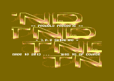
THE TND SWINGTRO
You may have studied a little on swinging a logo, but what about an actual PRACTICAL example, in which you can
display, swinging logos, a 1x1 scroll text and a flashing 1-liner? - Also link something, Well back in 2013. I entered an
oldschool intro creation competition, where the objective was to create an oldschool intro for the compo. The SwingTro was born.
The binary and source code data shows you how the swingtro was created. It uses multiple interrupts and pointers, which take control of the logo swing. The swing code is read from column 64 - mainly because the position of the logo screen should be in the middle area. If the logo was elsewhere, it would look very odd and swing from the incorrect position.
The IRQ code consists of 9 IRQ raster interrupts linked to each other. The 9 rasters take control of the type of charset, and horizontal screen position modes required. The static lines require no charset multicolour mode set to the intro. A logo swinger requires its own value of its independent swingstore pointer, to control the smoothness of the swinging logo. Also the raster position where the smooth scroller is required is also controlled by a pointer. No matter whatever you need to code. You need to control some routines with pointers. This is how this swinging logo intro worked out :) The code is sort of self-explained. Enjoy!
View Source CodeDownload C64Studio Source and Binary Data